
Views: 0 Author: Site Editor Publish Time: 2026-07-31 Origin: Site


Executing tall cuts in Electrical Discharge Machining presents specific physical challenges, driven by the exponential difficulty of debris evacuation as Z-axis height increases. When processing thick materials, the distance dielectric fluid must travel to clear microscopic swarf from the kerf becomes a severe bottleneck. If the flushing strategy fails, the consequences hit the shop floor immediately: frequent wire breakage, severe wire bowing resulting in a barrel-shaped cut, secondary EDM pitting, compromised surface finish, and unpredictable machine downtime on high-value tooling blocks.
Successful deep-cut EDM requires moving beyond default machine parameters. Operators cannot rely on standard settings when workpiece thickness exceeds conventional limits. Achieving stable, continuous cutting means aligning targeted flushing strategies, dielectric fluid management, and specific machine capabilities. Utilizing a specialized Wire EDM for Thick Workpieces ensures the hardware and software are optimized to handle the extreme demands of deep-cut debris evacuation.
Pressure vs. Volume: High pressure alone is insufficient for tall cuts; maintaining high fluid volume with laminar flow is critical to prevent cavitation and wire vibration.
Gap Clearance is King: Strategic wire selection and adaptive machining parameters must work in tandem with flushing to maintain an adequate spark gap for debris removal.
Hardware Dependencies: Effective flushing in tall workpieces requires a rigid Z-axis, perfectly aligned upper and lower nozzles, and high-capacity filtration systems.
Thermal Stability: Submerged cutting combined with synchronized coaxial flushing provides the most stable environment for thick workpiece accuracy.
Boundary Control: Maintaining flushing pressure requires preventing fluid escape; start-hole drilling and physical boundary shields are mandatory for extreme heights.
Inside a deep kerf, fluid dynamics change drastically compared to shallow cuts. As dielectric fluid enters from the upper and lower nozzles, pressure drops significantly towards the center of a thick workpiece. This creates a "dead zone" of near-zero velocity where debris accumulates rather than flushing out. Standard flushing parameters are not designed to push fluid through such a long, narrow channel effectively, leading to stagnation in the middle of the cut.
When debris stagnates, a phenomenon known as "debris bridging" occurs. Trapped swarf particles create a conductive path across the spark gap, causing secondary electrical discharges or arcing. This localized concentration of energy rapidly degrades the wire, leading to breakage and leaving severe gouges on the workpiece surface. Applying standard high-pressure settings without proper nozzle sealing induces fluid turbulence and cavitation, which vibrates the wire and destroys dimensional accuracy.
The "edge effect" further complicates flushing. Cutting close to a workpiece boundary or starting from an open edge allows dielectric fluid to escape laterally. When the fluid escapes, internal kerf pressure drops to near zero, completely neutralizing the flushing action. This is why edge-starts on tall workpieces frequently result in immediate wire breaks and unstable cutting conditions.
The ideal state of the spark gap in a tall cut involves consistent dielectric strength, rapid ionization and de-ionization cycles, and continuous swarf removal. The fluid must flow smoothly through the entire length of the cut, carrying away debris and heat without disrupting the wire's position. Achieving this balance requires precise control over fluid volume, pressure, and nozzle alignment.
Success in deep-cut EDM is measured by specific baseline metrics. Acceptable wire bowing tolerances should be strictly maintained, typically aiming for less than 10 µm of barreling over a 300 mm height. The machine must be capable of continuous cutting for hours without wire breakage. Dimensional accuracy must remain consistent from the top to the bottom of the cut, ensuring the final part meets exact specifications.
Metric | Standard Cut Target | Tall Cut Target (>300mm) |
|---|---|---|
Wire Bowing (Barreling) | < 5 µm | < 10 µm |
Continuous Cut Time | 4-6 hours | 12+ hours |
Flushing Pressure Drop | Minimal | Requires Adaptive Control |
Coaxial flushing utilizes synchronized upper and lower nozzles directly aligned with the wire path. This configuration directs fluid straight into the kerf from both ends, maximizing penetration into the deep cut zone. To maintain fluid velocity and prevent jet divergence, operators must minimize the standoff distance, keeping the nozzles within 0.1 mm to 0.5 mm of the workpiece surface. This tight clearance forces the fluid into the cut rather than allowing it to spray outward.
Extreme pressure comes with trade-offs. While high pressure helps clear the kerf, it also risks inducing wire vibration. If the pressure from the nozzles is unbalanced or excessively high, it pushes the wire out of alignment, causing dimensional errors. Operators must carefully balance pressure and volume to achieve effective flushing without compromising wire stability.
Fully submerged cutting is generally necessary for thick workpieces to maintain thermal equilibrium. The massive amount of heat generated during a long cut causes significant workpiece distortion if not properly managed. Submerging the entire block in dielectric fluid stabilizes the temperature, ensuring consistent dimensions throughout the machining process.
A submerged environment actively assists the primary flushing jets. It provides a stable ambient fluid pressure around the cut, reducing splashing and preventing air entrapment in the kerf. Air bubbles in the cut zone disrupt the spark gap and cause erratic cutting. Submersion ensures the kerf remains filled with fluid, enhancing the effectiveness of the upper and lower flushing nozzles.
To prevent dielectric fluid from escaping the kerf on entry and exit paths, physical containment methods are required. Custom magnetic flush plates or workpiece wrapping seal the open edges of the cut. By blocking the fluid's escape routes, these containment methods maintain high internal kerf pressure, forcing the fluid to travel vertically through the cut and carry away debris.
Drill a start hole well within the material boundary.
Thread the wire and verify nozzle standoff distance (0.1mm - 0.5mm).
Apply magnetic flush plates if cutting within 10mm of an edge.
Initiate submerged tank fill and verify ambient fluid stability.
Pre-drilled start holes are critical for maintaining 360-degree flushing containment during initial cut penetration. Starting from a drilled hole ensures the fluid is completely trapped within the workpiece, maximizing flushing efficiency from the very beginning. Edge-starts should be avoided on thick workpieces whenever possible, as they inherently compromise flushing pressure.
Modern machines utilize adaptive control technologies that monitor gap voltage in real-time. When these systems detect debris accumulation, indicated by a drop in gap voltage, they automatically adjust flushing pressure and feed rates. This dynamic response prevents wire breaks by clearing the kerf before the debris concentration becomes critical.
Pulsed flushing techniques are employed to break up debris clogs. Instead of applying continuous high-pressure stress on the wire, the machine pulses the flushing fluid, creating a hammering effect that dislodges stubborn swarf. This method effectively clears the cut zone while minimizing the risk of wire vibration and bowing.
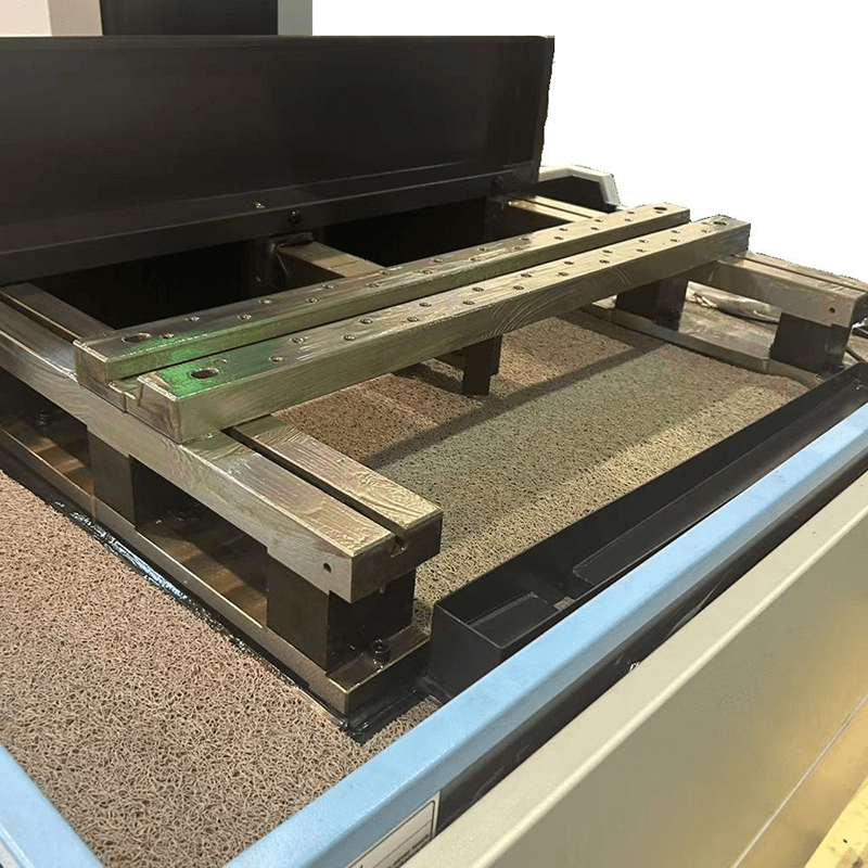
When selecting a Large Travel Wire EDM Machine for tall cuts, structural rigidity is paramount. The Z-axis must be exceptionally rigid to prevent deflection when the upper head is extended to its maximum height. Thermal compensation mechanisms are necessary to counteract the heat generated during prolonged cutting cycles. The worktable must be heavy-duty, capable of supporting massive blocks without sagging or shifting.
The pump and plumbing systems must handle the demands of deep-cut flushing. Dual-pump systems, programmable flow meters, and independent pressure controls for the upper and lower heads are essential features. Extended cutting runs on thick workpieces accelerate wear on upper and lower diamond guides. Machines must be equipped with robust guide-holding assemblies to maintain precise wire alignment over long durations.
Fluid cleanliness is disproportionately important in thick cuts. Dirty fluid increases the conductivity of the dielectric, raising the risk of secondary arcing across the long spark gap. Maintaining sub-5-micron filtration is necessary to ensure the fluid remains clean enough to support stable cutting. High-capacity resin tanks are required to maintain optimal fluid conductivity throughout the process.
Continuous high-load cutting depletes deionization (DI) resin rapidly. Operators manage this depletion by monitoring specific resistivity targets, typically keeping the fluid between 50,000 and 100,000 ohm-cm. Integrated chiller units manage the massive heat generated during prolonged thick cuts, preventing thermal expansion of the machine components and the workpiece.
Advanced generator technology is a core component of a High Efficiency Wire EDM system. Anti-Electrolysis (AE) power supplies utilize AC-based generators to prevent cobalt depletion in carbide and oxidation in steel during extended cycle times. This technology protects the metallurgical integrity of the workpiece during the long hours required for tall cuts.
Modern digital generators feature debris-sensing spark control. These systems detect real-time impedance drops in the spark gap, indicating a localized concentration of debris. The generator instantly adjusts the spark energy, reducing the risk of a wire break before the debris causes a short circuit. This rapid response maintains continuous cutting in deep kerfs.
Standard brass wire struggles in deep cuts due to its lower tensile strength and slower cutting speeds. Zinc-coated or stratified wires are generally preferred for thick workpieces. Coated wires sustain higher cutting speeds and create a slightly wider kerf. This wider kerf inherently improves flushing fluid penetration, allowing more volume to enter the cut and evacuate debris more effectively.
Tensile strength is a critical requirement to resist wire bowing under high flushing pressures. Wire diameter optimization plays a significant role. While 0.20 mm or 0.25 mm wires are common, larger diameters like 0.30 mm are preferred for tall cuts. The larger diameter provides higher tensile capacity to withstand aggressive flushing and creates wider flushing channels for better debris removal.
Wire Type | Diameter | Tensile Strength | Best Application |
|---|---|---|---|
Standard Brass | 0.25 mm | 900 N/mm² | Standard cuts < 150mm |
Zinc-Coated | 0.30 mm | 1000 N/mm² | Tall cuts 150mm - 300mm |
Molybdenum | 0.18 mm | >1900 N/mm² | Extreme heights, high-speed roughing |
A Molybdenum Wire EDM Machine offers a specific use case for processing thick workpieces. These machines utilize high-speed, reciprocating molybdenum wire. The extreme tensile strength of molybdenum allows for much higher tension settings compared to brass. This high tension effectively resists the deflection caused by aggressive flushing and the physical challenges of tall workpiece heights.
While molybdenum machines excel at roughing thick materials efficiently, there are trade-offs to consider. The surface finish capabilities may not match those of high-end brass wire machines. The operational efficiency of using reusable wire in high-volume roughing of thick materials often justifies the investment for specific manufacturing environments.
High flushing pressure combined with long wire spans frequently leads to harmonic vibration and bowing. This bowing causes dimensional inaccuracies, typically resulting in a barrel-shaped cut. To mitigate this risk, operators implement strict wire tension protocols. Utilizing specialized wire guides designed for tall cuts helps maintain alignment. Programming initial roughing passes with conservative feed rates establishes a stable kerf before increasing cutting speed.
Uneven flushing pressure between the top and bottom of the workpiece causes tapering and inconsistent surface finishes. The top and bottom edges receive better flushing than the center, leading to variations in the cut quality. To correct this, utilize multi-pass cutting strategies. Perform one roughing pass followed by multiple skimming passes with reduced flushing pressure and lower energy settings to refine the geometry and surface finish.
As the wire changes direction in tight corners, the local flushing dynamics shift abruptly. This shift leads to over-cutting or wire lag, washing out the intended geometry. To mitigate this issue, utilize path-dependent feed rate reduction. Synchronizing flushing pressure attenuation during radius transitions ensures the wire remains stable and the corner geometry is accurately maintained.
Conduct a test cut on a representative thick block to monitor wire breakage frequency and center-cut dimensional accuracy.
Upgrade filtration systems to sub-5-micron capacity to handle the increased debris load from tall cuts.
Implement magnetic flush plates or physical boundary shields when cutting near the edge of thick workpieces.
Switch to 0.30mm zinc-coated wire or evaluate molybdenum options for cuts exceeding 300mm in height.
A: Standard machines typically handle 10 to 16 inches effectively. Specialized Z-axis options extend this capacity significantly, provided the flushing systems, pumps, and filtration are upgraded to manage the increased debris load and fluid volume required for taller cuts.
A: Excessive flushing pressure pushes the wire out of its vertical alignment, creating a barrel-shaped cut. Operators balance the fluid pressure required to clear debris with the wire's tensile strength and tension settings to maintain a straight cut path.
A: The middle of a thick workpiece becomes a "dead zone" where upper and lower flushing streams meet or fail to penetrate fully. This causes debris to accumulate, leading to localized short circuits and rapid wire degradation, ultimately causing breakage.
A: Yes, larger diameter wires create a wider kerf. This wider channel allows more dielectric fluid to enter the cut zone, improving debris evacuation. Larger wires also offer higher tensile strength to resist bowing under high flushing pressure.
A: Standard operational ranges are typically 50,000 to 100,000 ohm-cm. Maintaining strict conductivity is necessary in thick cuts to prevent erratic sparking and secondary arcing across the long spark gap, which damages the workpiece and breaks the wire.
A: Molybdenum machines use high-speed reciprocating wire, which naturally aids in pulling debris out of the kerf. Their flushing systems are optimized for rapid, high-volume debris removal during roughing, rather than the ultra-fine, low-pressure flushing used for precision skimming.
A: To prevent fluid from escaping laterally, operators use sacrificial start blocks, magnetic flushing plates, or wrap-around containment shields. These physical barriers keep the dielectric jet contained within the kerf, maintaining the pressure needed to clear debris vertically.
 HB400
HB400  HB600
HB600  HB800
HB800  LA350A
  LA500A
  LA800
LA800  EB450
EB450  EA500A
  EB650N
  DS703C
  SK450
SK450 


