
High-precision manufacturing relies on electrical discharge machining to achieve complex geometries, but selecting the wrong equipment directly inflates scrap rates, cycle times, and consumable waste. Evaluating capital equipment in a saturated market requires separating marketing claims from mechanical realities. Buyers must balance the need for sub-micron tolerances against facility constraints, operator expertise, and production volume demands. A poorly specified machine leads to broken wire during unattended shifts, unacceptable surface finishes on critical components, and constant operator intervention. This guide provides a technical evaluation framework for shortlisting and selecting a Brass Wire EDM system. We focus on mechanical architecture, generator technology, wire handling capabilities, and long-term operational viability to ensure the equipment meets strict shop floor requirements.
Precision vs. Speed Trade-offs: Machine architecture (linear motors vs. ball screws) and generator technology dictate the balance between aggressive roughing speeds and fine surface finishes.
Wire Handling Dictates Autonomy: Reliable Automatic Wire Threading (AWT) and precise tensioning systems for standard brass wire are non-negotiable for unattended, "lights-out" machining.
Flushing is Critical to Performance: High-pressure, adaptive flushing systems are required to prevent wire breakage and maintain cutting stability in thick or stepped workpieces.
Establishing baseline production metrics dictates how the machine will function on the shop floor. High-volume production demands robust automation, massive spool capacities, and continuous wire feeding mechanisms that rarely fail. Rapid prototyping requires fast setup times, flexible workholding, and intuitive programming interfaces to handle high-mix, low-volume workflows. Specialized tool-and-die work prioritizes extreme accuracy and superior surface finishes over raw cutting speed. Identifying the primary application prevents over-specifying a machine with unnecessary automation or under-equipping a facility that needs sub-micron repeatability.
Acceptable tolerance bands dictate the mechanical rigidity required from the machine casting and drive systems. Holding +/- 0.0002″ demands strict thermal control, high-end linear drives, and a highly stable dielectric fluid temperature. Tighter tolerances require multiple skim passes after the initial roughing cut. Each additional skim pass removes microscopic amounts of material, improving the surface finish (Ra/Rz values) but significantly extending the overall cycle time. Operators must balance the desired surface integrity against production deadlines, knowing that a four-pass cut takes exponentially longer than a two-pass cut.
Specific geometry requirements directly influence machine selection and consumable choices. Minimum inside corner radii depend entirely on the supported wire diameters. Most machines accommodate diameters ranging from 0.004" to 0.012". Smaller wires cut tighter corners but break more easily under aggressive flushing pressure. Larger wires handle higher generator power for faster roughing but leave larger corner radii that may require secondary machining operations.
Wire Diameter (Inches) | Minimum Inside Corner Radius (Inches) | Typical Application |
|---|---|---|
0.004" | 0.0025" - 0.003" | Medical devices, micro-geometries |
0.006" | 0.0035" - 0.004" | High-precision aerospace components |
0.008" | 0.0045" - 0.005" | Standard tool and die work |
0.010" | 0.0055" - 0.006" | General production, thick workpieces |
0.012" | 0.0065" - 0.007" | Aggressive roughing, massive steel blocks |
Maximum part sizes determine the necessary X, Y, and Z-axis travels. You must evaluate the largest block of material you plan to cut, factoring in the extra clearance needed for fixturing clamps and flushing nozzles. The Z-axis travel is particularly critical for tall workpieces. Wire tension and flushing dynamics change drastically over longer spans. A 15-inch tall block of D2 tool steel requires significantly higher flushing pressure to clear debris from the middle of the kerf compared to a 2-inch plate.
Worktable weight limits matter just as much as physical dimensions. Machining heavy steel blocks or exotic alloys requires immense structural rigidity. Excessive weight causes microscopic deflection in poorly supported tables or cantilevered arm designs. This deflection ruins dimensional accuracy, regardless of the machine's electronic precision. Review the base casting design to ensure it supports the heaviest expected loads without compromising the geometric alignment of the lower arm.
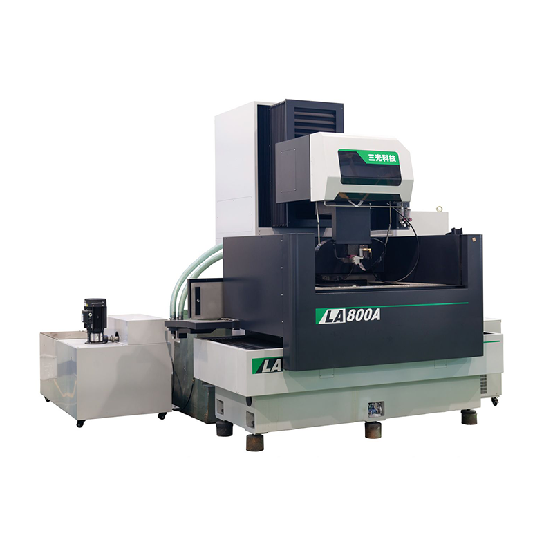
The structural integrity of a CNC Brass Wire EDM starts with its base casting. Meehanite cast iron provides excellent thermal stability and vibration dampening, making it the industry standard for high-end machines. Polymer concrete offers superior thermal inertia but alters the machine's weight distribution and requires different foundation preparation. The right base material prevents environmental temperature fluctuations from warping the structural geometry during 40-hour cutting cycles.
Fully submerged cutting environments provide distinct advantages over coaxial flushing. Submerging the workpiece stabilizes its temperature. The surrounding dielectric fluid absorbs the intense heat generated by the spark gap. This thermal regulation prevents material expansion during extended machining hours. Submersion also dampens wire vibration, improves debris evacuation, and reduces the risk of wire breakage when cutting near the edge of a workpiece.
Certain applications make submerged machining mandatory. High-taper cutting exposes the wire to unequal flushing pressures from the upper and lower nozzles. A submerged tank equalizes this pressure, reducing the risk of wire breaks. Extreme precision work also relies on the thermal consistency of a full tank. Non-submerged cutting works for thin plates or quick roughing operations, but it lacks the stability required for sub-micron accuracy on thick parts.
The drive system translates CNC commands into physical movement. Understanding the mechanical realities of each system helps predict long-term performance and maintenance requirements.
Feature | Ball Screws | Linear Motors |
|---|---|---|
Friction & Wear | High friction; wears over time | Frictionless; zero mechanical wear |
Backlash | Requires pitch error compensation | No mechanical backlash |
Long-term Accuracy | Degrades with mechanical use | Sustained indefinitely |
Maintenance | Requires regular lubrication | Virtually maintenance-free |
Traditional ball screws rely on physical contact between the screw and the nut. They suffer from wear, backlash, and thermal expansion caused by friction. Controllers use pitch error compensation to mask these physical flaws, but accuracy inevitably degrades as the mechanical components wear down. Linear motors utilize magnetic fields for frictionless movement. They maintain sustained accuracy over years of operation. While linear motors carry an initial premium, they eliminate the maintenance downtime associated with replacing worn ball screws and recalibrating the axes.
The processing power of the CNC unit dictates how smoothly the machine executes complex toolpaths. Advanced controllers feature high-speed look-ahead capabilities. They anticipate sharp corners and automatically adjust wire feed rates, tension, and generator power before the wire reaches the corner. Real-time path adjustments prevent wire breakage and eliminate corner washout, ensuring sharp, accurate geometry.
Automation readiness determines how easily the machine integrates into larger production cells. Look for macro-programming compatibility and open communication protocols like MTConnect. Robotic part loading requires automated drop-doors, precise pallet clamping systems (like System 3R or Erowa), and pneumatic chucks. The controller must seamlessly communicate with external robotic arms and cell management software to facilitate continuous, unattended production across multiple shifts.
Consumable compatibility drives operational flexibility. Evaluate how the machine handles standard 60/40 copper-zinc brass wire. This alloy provides a reliable baseline for most applications, offering a good balance of tensile strength and conductivity. You must also assess the system's adaptability to coated wires, such as zinc-coated or stratified wires, if production needs pivot toward higher cutting speeds or specialized aerospace alloys.
Reliable Automatic Wire Threading (AWT) enables unattended shifts. Examine the mechanics of the AWT system closely. Submerged threading capabilities save massive amounts of time by eliminating the need to drain and refill the tank every time the wire breaks or moves to a new start hole. Advanced systems utilize an annealing process. They run a current through the wire to heat it, stretch it, and form a sharp, bullet-like tip before cutting it. This improves insertion accuracy through small start holes and thick workpieces.
AWT failure during a "lights-out" shift halts production entirely, leaving machines sitting idle for hours. Evaluate vendor claims regarding threading success rates carefully. Look for systems equipped with air jets or high-pressure water jets that guide the wire through the lower nozzle. A robust AWT system automatically cuts the wire, returns to the start hole, and attempts re-threading multiple times if a break occurs, ensuring the machine keeps running.
Closed-loop wire tensioning systems prevent breakage during aggressive flushing. The machine must monitor and adjust tension dynamically using dual pinch rollers and servo-controlled brake motors. High-pressure flushing pushes against the wire, creating a bow effect in the middle of the cut. Precise tension control pulls the wire taut, maintaining dimensional accuracy across the Z-axis and preventing the wire from dragging on the workpiece.
The machine must adapt to different wire tensile strengths. Hard brass possesses high tensile strength (typically over 900 N/mm²). It resists deflection, making it ideal for straight, high-speed roughing and skimming. Soft brass features lower tensile strength (around 400-500 N/mm²). It bends easily, providing the flexibility needed for extreme taper angles up to 45 degrees. The tensioning system must automatically adjust feed rates and pull force based on the selected wire type to prevent snapping soft wire or under-tensioning hard wire.
The wire guide system dictates how easily operators can switch between wire diameters. Split guides open automatically, simplifying the AWT process and allowing for easy clearance of debris. Round diamond guides offer superior longevity and precision, holding the wire exactly on center, but require manual swapping when changing wire sizes. Evaluate the ease of conversion to minimize setup downtime when switching from a 0.010" wire for roughing to a 0.004" wire for micro-machining.
Physical surface area per unit length impacts guide wear. Smaller wires concentrate friction on a narrower band of the diamond guide. The guide assembly must feature adequate flushing to prevent particulate buildup. Microscopic brass flakes can accumulate in the guides, causing friction spikes that lead to premature wire breakage and erratic tension readings.
Spool capacity directly limits unattended run time. Calculate the correlation between your average wire feed rate and the physical spool size. Standard machines accept 16 lb (8 kg) spools, which typically provide 30 to 40 hours of continuous cutting depending on the feed rate. Upgrading to 35 lb or 60 lb spool configurations drastically increases continuous machining hours, allowing for true weekend-long unattended operation. Larger spools require robust tensioning motors and pre-feed mechanisms to pull the heavier mass without inducing wire vibration or stretching the wire before it reaches the cutting zone.
The spark generator and dielectric fluid management system form the heart of the EDM process. Together, they dictate cutting speed, surface integrity, and consumable efficiency. A high-end mechanical frame is useless without a generator capable of delivering precise, controlled sparks.
Modern generators feature adaptive power control. They automatically modulate spark energy when encountering changing workpiece thicknesses. Cutting through a solid 4-inch block requires high power. When the wire enters a cross-hole or a stepped feature, the sudden lack of material causes unstable sparking and concentrates the energy on a smaller surface area. Adaptive generators sense this gap voltage change instantly.
They drop the power output to prevent wire breakage and maintain a consistent overcut. Once the wire re-enters solid material, the generator ramps the power back up. Optimized pulse durations also reduce the recast layer (white layer) left on the workpiece surface. Shorter, higher-frequency sparks remove material cleanly, minimizing the micro-cracking associated with excessive thermal damage, which is critical for aerospace and medical components.
Fluid dynamics clear microscopic debris from the kerf. If debris accumulates, it causes secondary sparking between the wire and the suspended particles. This damages the surface finish, reduces cutting speed, and leads to immediate wire failure. High-pressure flushing systems force clean dielectric fluid through the cut, evacuating particles rapidly and cooling the wire.
Programmable flushing nozzles maintain optimal flow. They hug the top and bottom of the workpiece closely, often within 0.005" of the surface. The system must deliver high pressure without inducing wire vibration. Advanced machines automatically adjust flush pressure based on the thickness of the material and the aggressiveness of the spark generator, using inverter-driven pumps to supply exactly the right amount of fluid.
Generators scale power output to match electrode conductivity. Standard 60/40 brass provides steady, reliable sparking. Zinc-coated wires feature higher conductivity and a lower melting point on the outer layer. The generator must recognize this difference. It increases the spark frequency to vaporize the zinc coating, which carries away heat and allows for maximum cutting speeds, often 20% to 30% faster than bare brass.
Pushing maximum current requires faster wire feed speeds to prevent the wire from burning through. Features that optimize wire feed speeds reduce consumable waste. The generator analyzes the spark gap stability and slows the wire feed to the absolute minimum required to maintain cutting stability. This prevents operators from running the wire at 100% speed unnecessarily, conserving wire on long cuts.
Installing a new machine involves physical and operational hurdles. Proper preparation mitigates adoption risks and ensures the equipment performs to its specifications from day one.
Sub-micron accuracy requires strict environmental controls. Ambient temperature regulation must remain within ±1°C. Thermal expansion of the machine casting or the workpiece ruins tight tolerances. A 10-inch steel block expands significantly with just a few degrees of temperature change. You may need isolated foundations to prevent external vibrations from stamping presses, CNC mills, or forklifts from transferring into the cut and causing surface finish striations.
Clean, stable electrical power is mandatory. Voltage spikes or drops disrupt the spark generator and can crash the CNC controller. You will likely need power conditioners or isolation transformers. These devices guarantee a steady supply of electricity, protecting sensitive CNC boards and ensuring consistent cutting performance regardless of what other equipment is running in the shop.
Advanced EDM programming presents a steep learning curve. Proprietary CNC interfaces require dedicated training. Evaluate the quality of vendor-provided training programs. Hands-on instruction accelerates operator proficiency and reduces the likelihood of costly crashes or scrapped parts during the first few months of operation.
Look for intuitive, conversational programming features. These interfaces bridge skill gaps by allowing operators to input basic part dimensions, material types, and desired surface finishes. The controller then automatically generates the necessary G-code, wire tension settings, flushing pressures, and generator power parameters, reducing the reliance on highly specialized EDM programmers.
Vetting the OEM service infrastructure is critical. Machine downtime destroys production schedules and damages client relationships. Demand local technician availability and guaranteed response times. A strong Service Level Agreement (SLA) protects your operation. Ensure the vendor maintains a domestic spare parts inventory. Waiting weeks for a replacement circuit board, power contact, or specialized wire guide shipped from overseas halts production entirely.
Choosing the right equipment requires aligning machine architecture, generator capabilities, and AWT reliability with your specific production tolerances. You must look past marketing brochures and evaluate the mechanical realities of the system.
Utilize a matrix-based approach to compare shortlisted machines based on test-cut performance, mechanical specifications, and vendor SLAs.
Request custom test cuts using your own complex part files to verify accuracy, corner radii, and surface finish claims on your actual material.
Demand a detailed time-study from the vendor to confirm cycle times and wire consumption rates for your specific applications.
Physically inspect the vendor's service and parts facility before issuing a purchase order to guarantee long-term support and parts availability.
A: Modern machines typically hold tolerances ranging from +/- 0.0002″ to +/- 0.0001″. Achieving the tighter end of this spectrum depends heavily on strict climate control, stable dielectric fluid temperature, rigid machine castings, and the use of high-quality wire and diamond guides.
A: Wire diameter dictates the minimum inside corner radius you can machine. Diameters typically range from 0.004" to 0.012". Smaller wires cut tighter corners but require specialized tensioning systems and lower generator power to prevent breakage during the cut.
A: Yes. Most modern machines accommodate zinc-coated or specialized stratified wires. Operators must adjust CNC parameters, modify tensioning settings, and sometimes swap wire guides to handle the different tensile strengths and conductivity levels of coated wires.
A: Hard brass provides the straightness and tension resistance needed for high-speed roughing and skimming on vertical cuts. Soft brass yields the flexibility required for high-taper cutting (up to 45 degrees) without snapping under angular stress at the guides.
A: Linear motors utilize magnetic fields for frictionless movement. This eliminates mechanical backlash, physical wear, and the need for pitch error compensation, ensuring sustained long-term precision without the maintenance downtime associated with replacing worn ball screws.
A: Installations often require strict ambient temperature control (±1°C), reinforced flooring to handle machine weight and isolate vibration, dedicated power conditioners for electrical stability, and proper dielectric fluid disposal protocols to handle the deionized water.


 HB400
HB400  HB600
HB600  HB800
HB800  LA350A
  LA500A
  LA800
LA800  EB450
EB450  EA500A
  EB650N
  DS703C
  SK450
SK450 


