
Views: 0 Author: Site Editor Publish Time: 2026-08-05 Origin: Site


In precision machining, sharp corners and complex geometries expose the physical limitations of standard electrical discharge machining. Operators frequently encounter wire lag, corner washout, or unacceptable dimensional errors when navigating tight radii. When cutting tight corners, the sudden change in direction alters the Material Removal Rate (MRR) and flushing dynamics. This disruption leads to wire deflection, thermal distortion, vertical taper errors, and ultimately, part rejection. Modern CNC Molybdenum Wire EDM systems address these physical limitations through adaptive algorithms, dynamic tensioning, precise power modulation, and high-resolution motion systems. Evaluating how a specific CNC Molybdenum Wire EDM Machine manages these variables is critical for manufacturers looking to invest in high-tolerance, high-efficiency production tooling. Mastering these control variables separates acceptable rough cuts from precision components ready for final assembly.
Adaptive Feed and Power Control: Advanced CNC systems automatically adjust feed rates and discharge energy at corners to compensate for wire lag and maintain vertical straightness.
Dynamic Tension & Flushing Optimization: Integrated CNC controls synchronize wire tensioning brake systems and flushing pressure to minimize wire vibration during sharp directional changes.
Vertical Straightness Compensation: Corner inaccuracies are not just 2D profile errors; modern CNCs control U/V axis offsets to eliminate vertical tapering ("belly" distortion) at corners.
Outside Corner Design Strategy: Programming micro outside corner radii through the CNC can eliminate the need for costly multi-pass skim cuts while preserving structural integrity.
Multi-Pass Optimization in Reusable Systems: Utilizing programmed skim cuts via precision wire cutting EDM significantly improves surface roughness and mitigates stress-induced deformation, even with degrading molybdenum wire.
Wire lag is a mechanical reality in electrical discharge machining. As the machine axes move, the center of the wire trails behind the upper and lower guides. This deflection occurs because of the continuous spark discharge forces pushing against the wire and the physical resistance of the dielectric fluid. During straight linear movements, this lag remains relatively constant and predictable. However, abrupt directional changes at corners severely disrupt this equilibrium. The trailing wire center fails to pivot at the exact same moment as the guides, causing the wire to drag through the corner. This dynamic cuts an unintended radius, washes out internal corner geometries, or undercuts external edges.
This deflection creates a significant verticality gap. Wire lag distorts vertical straightness, generating a "belly" or taper error across the thickness of the workpiece. The center of the cut experiences a different corner radius than the top and bottom faces near the guides. Without active compensation, this bowing effect ruins the dimensional accuracy of mating parts, particularly in thick workpieces where the unsupported wire length is greatest. For example, cutting a 100mm thick block of D2 tool steel amplifies the belly effect significantly compared to a 20mm plate.
Typical Wire Deflection Variables in Thick Workpieces | |||
Workpiece Thickness (mm) | Expected Center Deflection (mm) | Required U/V Axis Compensation | Flushing Pressure Adjustment |
|---|---|---|---|
20 | 0.005 - 0.010 | Minimal | Standard |
50 | 0.015 - 0.025 | Moderate | Reduced by 15% at corners |
100 | 0.030 - 0.050 | Aggressive | Reduced by 30% at corners |
150+ | 0.060+ | Maximum | Pulsed flushing required |
When a wire approaches and transitions through a sharp corner, the quantitative Material Removal Rate shifts dramatically. In a straight line, the wire engages the material with a consistent frontal surface area. At a corner, the engagement area changes. The wire slows down to navigate the pivot, but if the discharge power remains static, the energy concentrates into a much smaller, localized zone. This concentrated energy blasts away more material than intended, leading to severe over-machining or gouging at the pivot point.
Legacy control systems and manual setups fail to predict or compensate for these localized MRR spikes. They continue pumping high-amperage current into the cut even as the physical feed rate drops. Modern systems must dynamically map the MRR to the toolpath geometry, reducing spark energy proportionally as the wire decelerates into the corner and ramping it back up as it accelerates out. Managing this energy density is the only way to prevent corner overburn.
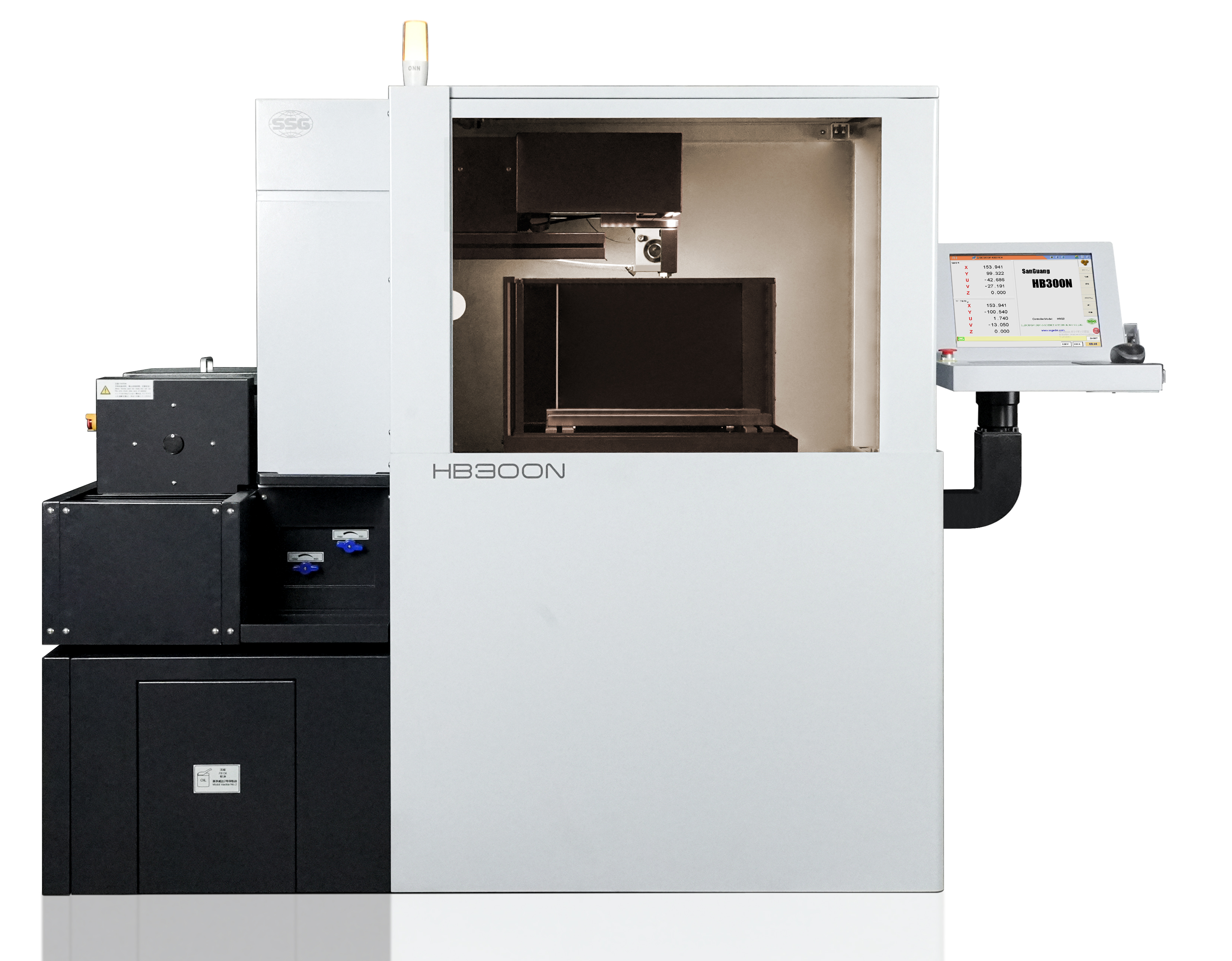
Modern CNC algorithms calculate exact deceleration profiles required as the wire approaches a corner and the corresponding acceleration curves as it exits. By analyzing the upcoming toolpath, the controller anticipates the exact moment the wire guides will change direction. It then adjusts the feed rate to ensure the trailing center of the wire catches up to the programmed path. Corner path interpolation techniques keep the wire engaged optimally without dwelling in one spot too long.
Look-Ahead Processing: The CNC scans multiple blocks of G-code ahead to identify upcoming sharp angles.
Deceleration Ramp: The machine gradually reduces the X/Y axis feed rate before reaching the pivot point.
Power Modulation: Simultaneously, the generator drops the peak current and increases off-time to prevent overburn.
Corner Execution: The guides execute the pivot while the trailing wire catches up.
Acceleration Ramp: Feed rate and power are restored to straight-line parameters as the wire exits the corner.
Closed-loop feedback systems play a critical role here. The CNC continuously monitors the average spark gap voltage. If the voltage drops—indicating the wire is getting too close to the workpiece and risking a short-circuit—the system instantly overrides the programmed feed rate. This real-time adjustment prevents wire breakage and maintains a stable discharge environment through the most complex corner geometries.
Advanced CNC software directly integrates with the machine's physical electromagnetic wire brake system. By briefly increasing wire tension exactly at the corners, the system reduces amplitude vibration and minimizes 3D deflection. A tighter wire resists the lateral forces of the spark discharge much better than a slack one, forcing the center of the wire to follow the guides more closely during sharp pivots.
Maintaining consistent tension presents specific challenges in a reusable Molybdenum Wire EDM setup. Because the wire is constantly wound back and forth on a drum, the tensioning mechanism must account for the changing spool diameter and the reversing direction. The CNC dynamically adjusts the braking force to ensure uniform tension regardless of the drum's rotational direction, preventing tension spikes that could snap the wire or drops that could cause severe corner washout.
Flushing pressure directly impacts wire vibration and debris evacuation. High-pressure dielectric fluid is necessary to clear microscopic chips from the kerf during fast, straight cuts. However, at sharp corners, this same high pressure can physically push the wire off its intended path, exacerbating wire lag and corner deformation. CNC controls automatically reduce flushing pressure during tight cornering.
This modulation is synchronized with cutting speed, discharge power, and the specific nozzle-to-workpiece distance. As the machine decelerates into a corner and drops the discharge energy, less debris is generated. The CNC lowers the pump pressure accordingly, allowing the wire to stabilize. Once the corner is cleared and full power resumes, the flushing pressure ramps back up to maintain cutting efficiency.
Achieving true sharp edges and superior surface finishes requires multi-pass strategies. A standard operation involves a high-energy roughing pass followed by multiple low-power skim cuts. In Precision Wire Cutting EDM, these skim cuts remove the microscopic recast layer and correct the vertical taper left by the roughing pass. The CNC interface must allow operators to program distinct power settings, tension levels, wire offsets, and feed speeds for each consecutive pass.
Evaluating a machine's multi-pass repeatability involves checking its positioning accuracy over time. This is especially critical when compensating for molybdenum wire wear. Because the wire diameter shrinks slightly with each use, the CNC must automatically recalculate the wire offset for every skim cut to ensure the final dimensions remain within strict tolerances. Operators must verify that the machine's software handles these offset calculations seamlessly without requiring manual intervention between passes.
Standard Multi-Pass Parameters for 0.18mm Molybdenum Wire | ||||
Pass Number | Purpose | Relative Power Level | Wire Offset (Approx) | Surface Finish (Ra) |
|---|---|---|---|---|
1 | Roughing | 100% | 0.110mm | 2.5 - 3.0 µm |
2 | First Skim | 40% | 0.095mm | 1.5 - 2.0 µm |
3 | Second Skim | 15% | 0.091mm | 0.8 - 1.2 µm |
4 | Final Polish | 5% | 0.090mm | < 0.8 µm |
The foundation of sub-micron corner accuracy lies in the machine's motion control system. Traditional stepper motors and rotary servos rely on ball screws, which inherently introduce mechanical backlash, friction, and wear over time. Advanced linear motors, paired with high-resolution linear glass scales, eliminate these mechanical linkages. They provide friction-free, backlash-free movement, dictating exactly how faithfully the machine executes the CNC's adaptive toolpaths.
When assessing a machine tool, mechanical rigidity, guide-way design, and thermal stabilization must be evaluated alongside the motion system. A highly responsive linear motor cannot compensate for a flexing machine frame or thermal expansion in the casting. Heavy-duty cast iron bases and temperature-controlled environments are required to maximize the benefits of advanced motion controls. Look for machines with thermally symmetrical designs that isolate heat-generating components from the main cutting area.
Physical expectations for corner radii are dictated by the molybdenum wire diameter—typically between 0.12mm and 0.18mm—plus the spark gap. It is physically impossible to cut an internal corner sharper than this combined radius. The CNC control manages the transition between high-speed straight lines and these micro-radii to prevent undercutting and localized thermal damage.
High-frequency, low-energy AC discharge settings are critical for achieving superior surface finishes at these intersections. By utilizing short-duration sparks, the CNC minimizes the heat-affected zone, preventing micro-cracking and ensuring the structural integrity of the corner remains intact. This is particularly important for aerospace and medical components where fatigue failure often initiates at sharp internal corners.
There is a strict inverse relationship between cutting speed and corner precision. Running high-amperage roughing passes on a High Efficiency Wire EDM Machine maximizes material removal but introduces significant wire lag and thermal distortion. Achieving tight tolerances requires trading that speed for the time-consuming process of multiple low-amperage skim cuts.
Implementing an outside corner strategy can mitigate this trade-off. By designing small outside corner radii into the part geometry rather than demanding perfectly sharp external angles, programmers can often eliminate the need for redundant skim cuts on outside edges. This strategy significantly lowers cycle times while maintaining necessary geometric tolerances. Operators must balance cycle times with tolerance requirements based on the functional application of the final part.
Molybdenum wire is prized for its high tensile strength and reusability, but it degrades over time. Tensile wear and gradual diameter reduction occur over multiple passes. Advanced CNC controls must track the usage time or distance of the wire and automatically calculate compensation values for the changing diameter. This ensures consistent kerf width, accurate offset calculations, and reliable corner geometry from the first part to the last.
The operational cost benefits of reusable molybdenum wire systems are substantial compared to single-use brass wire systems. However, these savings must be weighed against the stringent monitoring and offset recalibrations required for ultra-precision parts. If the CNC lacks robust wire wear compensation algorithms, the operator will spend excessive time manually adjusting offsets to prevent corner deviations. Regular micrometer checks of the wire diameter are mandatory for high-tolerance runs.
Machining complex corner geometries often releases internal residual stresses within the workpiece material, causing unexpected deformation. This risk is highest during the final cut-off phase when the part loses its structural connection to the main block. Mitigation strategies start before machining begins, including proper workpiece clamping and stress-relief heat treatments.
Pre-Machining Heat Treatment: Ensure all raw material undergoes proper stress relieving before EDM operations.
Strategic Clamping: Use precision vises and avoid over-tightening, which introduces mechanical stress.
Submerged Cutting: Keep the workpiece fully submerged in dielectric fluid to maintain a stable temperature.
Tab Placement: Program multiple small cut-off tabs rather than a single large one to distribute holding forces.
Final Pass Sequencing: Cut the tabs only after all skim passes on the main profile are complete.
The most advanced CNC capabilities are useless if operators lack the expertise to apply them. There is a significant risk of underutilizing a machine's potential due to insufficient training. Operators must understand how to manipulate specific corner-control parameters, including corner dwell times, power reduction percentages, tension overrides, and automatic taper compensation.
Facilities should standardize cutting conditions and build a proprietary database of CNC parameters tailored to their specific materials, thicknesses, and common corner geometries. This database reduces reliance on trial-and-error, ensuring consistent corner accuracy across different operators and shifts. Documenting successful parameters for difficult materials like carbide or inconel saves hours of setup time on future jobs.
Evaluate your current part geometries and identify specific areas where corner washout or vertical tapering causes assembly issues.
Standardize your programming approach by incorporating micro outside corner radii wherever design constraints allow to reduce skim cut times.
Build a material-specific parameter database that dictates exact feed deceleration, tension increases, and flushing reductions for sharp corners.
Mandate test cuts on your most complex profiles when upgrading equipment, demanding metrology reports that verify vertical straightness and corner radii accuracy.
A: The sharpest internal corner is limited by the wire radius plus the spark gap. For a standard 0.18mm molybdenum wire, the absolute minimum internal radius is typically around 0.10mm to 0.11mm.
A: Wire breakage at corners happens due to localized spikes in the Material Removal Rate. As the wire slows down to pivot, static discharge energy concentrates in a smaller area, overheating the wire and causing it to snap.
A: The CNC compensates by automatically decelerating the feed rate as it approaches a corner, reducing discharge power, and temporarily increasing wire tension to pull the trailing center of the wire back into alignment.
A: Yes. High flushing pressure can physically deflect the wire during sharp directional changes. Advanced CNCs automatically lower flushing pressure at corners to stabilize the wire and prevent washout.
A: Linear motors eliminate mechanical backlash and friction found in traditional ball screws. This provides frictionless, highly responsive motion control, which is essential for executing the micro-movements required for precise corner interpolation.
A: As reusable molybdenum wire wears, its diameter shrinks. If the CNC does not automatically adjust the wire offset to compensate for this reduction, the kerf width changes, leading to inaccurate corner dimensions and poor surface finishes.
 HB400
HB400  HB600
HB600  HB800
HB800  LA350A
  LA500A
  LA800
LA800  EB450
EB450  EA500A
  EB650N
  DS703C
  SK450
SK450 


