
Views: 0 Author: Site Editor Publish Time: 2026-08-05 Origin: Site


In complex precision machining, the primary bottleneck often shifts from machine execution to the time and expertise required for accurate path generation. Machining intricate geometries—such as variable tapers, asymmetrical top and bottom profiles, and micro-radii—introduces severe risks of wire breakage, dimensional inaccuracy, and excessive setup times. These risks are amplified when managing the unique wear characteristics of reusable wire systems. Mitigating these risks requires evaluating the specific CAM capabilities and onboard control features that automate complex calculations. This guide examines the critical programming features necessary to optimize a CNC Molybdenum Wire EDM setup for complex profile execution, balancing automation with necessary manual overrides to maintain strict tolerances.
Successful complex profile machining relies on strict, measurable metrics. Shop floors must minimize programming time per part, achieve first-time-right dimensional accuracy, and ensure predictable surface finishes across varying material thicknesses. Manual G-code programming quickly becomes a liability as part geometry advances beyond simple straight cuts. Transitioning from standard 2D contours to 4-axis independent profiles or multi-cavity progressive dies requires advanced software intervention. Human calculation cannot reliably manage the simultaneous interpolation of four independent axes while factoring in spark gap and wire wear.
Programming strategies differ significantly between inside and outside profiles. Internal cavities require precise pre-drill thread hole locations and auto-threading paths. You must program the wire to enter the workpiece, complete the contour, and manage the internal slug without causing a short circuit. External cuts involve open profiles, specific lead-in and lead-out lines, and edge starts. The entry and exit vectors dictate the final edge quality of the component. A poorly programmed lead-in will leave a visible witness mark on the finished part, requiring secondary polishing operations.
The physical realities of reusable molybdenum wire necessitate specialized programming offsets. Unlike single-pass brass wire systems, molybdenum wire experiences continuous progressive wear as it spools back and forth. Variable tension and decreasing wire diameter require dynamic compensation. Precision Wire Cutting EDM software must automatically adjust the cutting path offset to maintain tight tolerances across long cycle times. If the software assumes a static wire diameter, the final dimensions of a large punch or die block will taper out of tolerance by the end of the cut.
Furthermore, flushing conditions must be integrated into the programming logic. Complex profiles often involve varying workpiece thicknesses or stepped geometries. The CAM software should allow operators to program changes in flushing pressure and generator power at specific nodes along the toolpath. High-pressure flushing is required for thick sections to clear debris, while lower pressure prevents wire deflection in thin or delicate sections. Tying these physical machine parameters directly to the programmed toolpath ensures stable cutting conditions throughout the entire cycle.
When machining progressive die plates, the sheer volume of features demands a systematic programming approach. A single plate might contain dozens of punches, pilots, and clearance holes, each requiring different fits and clearances. Programming these manually invites human error. Advanced CAM systems allow programmers to apply templates to similar features, automatically generating the roughing and skimming passes, lead-ins, and slug retention tabs based on predefined shop standards. This standardization reduces programming time from hours to minutes and guarantees consistency across the entire die set.
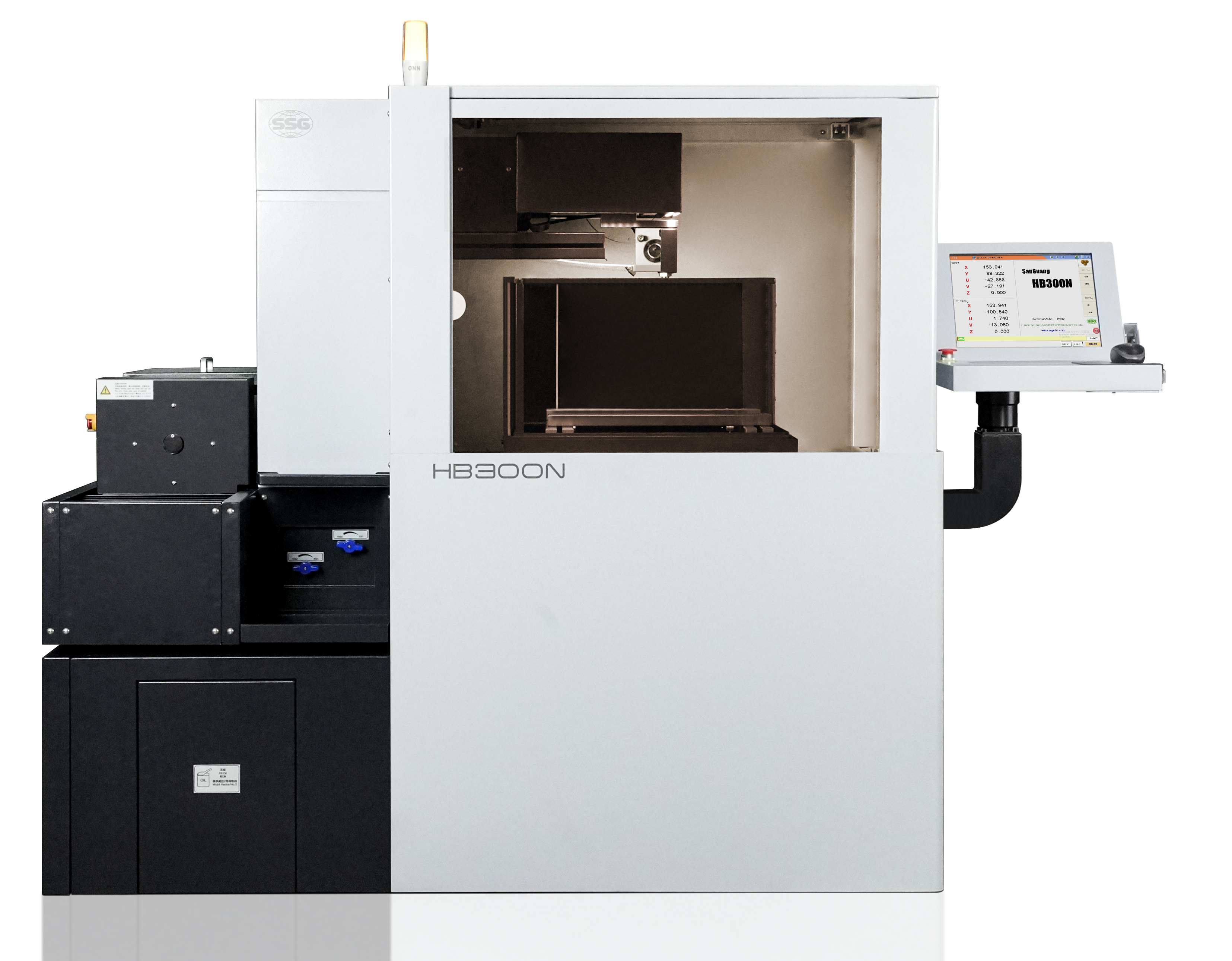
Modern CAM software provides model-driven feature extraction. This capability automatically identifies wireable features like pockets, open profiles, and tapers directly from solid models. Bypassing intermediate 2D DXF or DWG conversions reduces translation errors. Native 3D CAD model-driven machining ensures the toolpath perfectly matches the original design intent. When a design change occurs, the software updates the toolpath associatively, eliminating the need to start the programming process from scratch.
Advanced taper control requires robust 4-axis synchronization. Programming tools must manage independent XY (bottom) and UV (top) coordinate systems. Synchronization lines, or match lines, are critical. They prevent the wire from twisting and ensure accurate corner blending on asymmetrical shapes. Without precise synchronization, the wire will drag, causing dimensional failure. For example, transitioning from a square shape on the bottom of a part to a circular shape on the top requires the software to map specific points on the XY profile to corresponding points on the UV profile.
Dynamic corner control prevents wire deflection. CAM capabilities program automatic corner slowdowns to maintain dimensional accuracy on sharp micro-radii. The software adjusts feed rates and power settings as the wire navigates tight angles. Radial and tangential lead-ins eliminate dwell marks. These entry scars occur at the start and end points of a cut if the wire pauses or enters at a harsh angle. By programming a sweeping radial entry, the wire blends smoothly into the final profile, leaving a pristine surface finish.
Automated slug management secures internal material during cutting. Programming strategies include tabbing or micro-joints to retain the slug until an automated cut-off pass. No-core machining offers an alternative for small cavities. These pocketing routines destructively machine away internal material. This eliminates the need for manual slug removal, enabling safe, unattended operations. For large drop-outs, the software must calculate the center of gravity of the slug and place retention tabs strategically to prevent the slug from tilting and pinching the wire before the cut is complete.
Another critical feature is the ability to program variable land tapers. In extrusion dies or stamping tools, the die cavity often requires a straight land section followed by a relief taper. Programming this requires the software to output code that keeps the UV axes stationary while the XY axes move for the land, and then simultaneously move all four axes for the relief. Specialized wire EDM software handles these complex transitions seamlessly, whereas generic milling CAM often struggles to generate the correct G-code syntax for these specific machine movements.
| Programming Feature | Primary Function | Impact on Complex Profiles |
|---|---|---|
| Model-Driven Extraction | Identifies wireable features from 3D models | Eliminates 2D translation errors and speeds setup |
| 4-Axis Synchronization | Independent XY and UV plane control | Enables asymmetrical shapes and variable tapers |
| Dynamic Corner Control | Automates feed rate reduction at sharp angles | Prevents wire deflection and maintains micro-radii |
| No-Core Machining | Destroys internal cavity material entirely | Allows unattended operation without slug collisions |
| Variable Land Tapering | Programs straight lands followed by relief angles | Essential for extrusion dies and stamping tools |
Choosing the right programming environment dictates operational success. Generic, integrated milling and turning CAM suites often feature basic wire modules. These modules struggle with advanced wire dynamics. Dedicated, specialized wire EDM programming software manages technology tables, generator settings, power registers, and multi-pass scheduling far more effectively. A High Efficiency Wire EDM Machine requires software built specifically for spark erosion, not software adapted from chip-making processes.
Effective software maps specific programming features to production outcomes. Automated threading routines reduce machine downtime. Multi-pass programming wizards improve surface finish. Wire EDM Wizards guide operators step-by-step through setting up roughing, skimming, and finishing cuts. These wizards base their calculations on workpiece material and thickness, simplifying complex parameter selection. Instead of guessing the correct off-time and on-time for a 50mm thick piece of D2 tool steel, the operator selects the material and thickness from a database, and the software populates the optimal cutting conditions.
Wire wear compensation algorithms are vital for reusable wire systems. The software must handle kerf width adjustments over long cycle times. Programmable offset libraries adapt to the specific degradation curve of molybdenum wire. These libraries apply different compensation values across roughing and skimming passes to guarantee final part dimensions. If a roughing pass takes six hours, the wire diameter at the end of the pass will be smaller than at the beginning. The software must dynamically adjust the offset to prevent the part from becoming tapered.
Simulation and collision detection prevent catastrophic failures. True solid-model kinematic simulation is a strict requirement. The software must predict wire collisions with the workpiece, fixtures, or machine heads. This verification is particularly critical during extreme UV axis offsets where mechanical interference risks are highest. A good simulation module will show the exact movement of the upper and lower guide heads, alerting the programmer if the programmed taper angle exceeds the mechanical limits of the machine.
To properly evaluate software for your shop, follow these specific steps:
Post-processor compatibility presents a major implementation risk. Generic post-processors often generate inefficient or incompatible code for specific machine controllers. This leads to syntax errors, unpredictable machine behavior, and scrapped parts. Mitigate this risk by prioritizing CAM vendors with certified, machine-specific post-processors. Open-architecture systems that allow precise macro customization also provide a safeguard for a CNC Molybdenum Wire EDM Machine. You need the ability to tweak the post-processor to output specific M-codes for your machine's auto-threading or tank-fill routines.
Software overhead can overwhelm operators. Investing in feature-heavy software without adequate training leads to underutilization. Operators may revert to manual programming for simple tasks, defeating the purpose of the investment. Evaluate the presence of intuitive Wire EDM Wizards. These tools guide operators through standard setups while retaining advanced menus for complex edge cases. Training should focus on the specific features your shop uses daily, rather than trying to cover every obscure function in the software manual.
Balancing automation with manual override requires careful evaluation. Highly automated toolpath generation accelerates programming but can limit granular control. Operators often need to adjust cutting conditions like voltage, wire speed, and flush pressure at specific nodes along the toolpath to deal with poor flushing conditions or stacked plates. Ensure the programming environment allows manual insertion of condition-change codes. This manual intervention must not break the automated toolpath associativity. If the model changes, the manually inserted condition codes should remain attached to their specific geometric locations.
Another risk is poor integration with existing shop floor networks. The CAM software must be able to send programs directly to the machine control via Ethernet or RS-232 without requiring manual file transfers via USB drives. This ensures version control and prevents operators from running outdated or unapproved programs. Network integration also allows the CAM software to pull actual cutting data back from the machine, enabling programmers to refine their technology tables based on real-world performance.
The viability of machining complex profiles profitably hinges on software that bridges the gap between 3D design intent and the physical realities of wire EDM. Base your software and machine control selection on your specific mix of production volume and geometric complexity. High-mix, complex-geometry environments must prioritize model-driven CAM and robust 4-axis synchronization over basic onboard conversational controls.
A: 2-axis programming moves the wire vertically along the X and Y axes for straight cuts. 4-axis programming utilizes independent U and V axes at the top of the machine to tilt the wire. This allows for complex tapers and different shapes on the top and bottom of the workpiece.
A: The control software uses predefined wear curves and multi-pass offset programming to adjust the cutting path. It dynamically recalculates the toolpath offset, ensuring dimensional accuracy as the reusable molybdenum wire decreases in diameter during operation.
A: No-core machining is a programming strategy that erodes the entire internal cavity of a feature. It turns the material into chips and dust rather than leaving a solid slug. This method is ideal for unattended machining and avoiding slug-removal collisions.
A: Tailored entry and exit vectors, such as radial lead-ins, prevent the wire from dwelling in one spot too long. This continuous motion eliminates surface blemishes, entry scars, and micro-grooves at the start and stop points of the profile.
A: While some integrated CAM packages offer basic wire EDM modules, dedicated wire EDM software is required for complex parts. Specialized software handles unique parameters like wire threading, cutting conditions, spark generator settings, and independent 4-axis synchronization.
A: Simulation verifies toolpaths against the actual machine kinematics. It identifies potential collisions between the wire guides, the workpiece, and the fixturing during extreme taper angles before physical cutting begins, preventing costly machine damage.
 HB400
HB400  HB600
HB600  HB800
HB800  LA350A
  LA500A
  LA800
LA800  EB450
EB450  EA500A
  EB650N
  DS703C
  SK450
SK450 


