
Views: 0 Author: Site Editor Publish Time: 2026-08-03 Origin: Site


In high-tolerance manufacturing, the physical properties of the cutting tool dictate the ceiling of achievable precision. In wire electrical discharge machining (EDM), that ceiling is heavily influenced by a single, highly variable factor: wire tension. Inconsistent or improper wire tension leads to spatial deflection, microscopic vibrations, and wire breakage. For production managers and engineers utilizing a Molybdenum Wire EDM Machine, this translates to rejected parts, poor surface finishes, and unpredictable machine downtime that destroys operational margins. Mitigating these risks requires moving beyond basic operational guidelines and understanding the mechanical realities of tension control. Evaluating how a modern CNC Molybdenum Wire EDM Machine manages tension dynamically is a critical step in selecting equipment capable of meeting strict dimensional tolerances.
Tension Directly Controls Deflection: Optimal tension minimizes the "bowing" effect caused by electrostatic and hydrodynamic forces during the cutting process, directly impacting dimensional accuracy.
Dynamic Control is a Differentiator: Legacy mechanical tensioners are being replaced by closed-loop servo, electromagnetic hysteresis, or pneumatic systems that adjust tension in real-time to maintain stability.
The Bidirectional Challenge: Unlike single-use brass wire, molybdenum wire is reusable and runs on a reciprocating drum; tension must be regulated during high-speed direction reversals.
Surface Finish Relies on Vibration Mitigation: Proper tension dampens wire resonance, which is the primary culprit behind striations and poor Ra values on the finished workpiece.
Speed vs. Stability Trade-off: Maximizing cutting speed on a High Efficiency Wire EDM Machine requires a precise balance; over-tensioning leads to premature wire fatigue, while under-tensioning destroys accuracy at high feed rates.
Establishing the baseline requirement for Precision Wire Cutting EDM means maintaining a perfectly vertical or precisely angled wire path despite immense external forces. The cutting wire acts as a flexible electrode. If it deviates from the programmed toolpath, the resulting cut will mirror that deviation. On the shop floor, we see this manifest as parts that gauge fine at the top and bottom edges but fail inspection in the middle of the cut.
During the cutting process, the wire faces two primary lateral forces. Hydrodynamic forces emerge from the pressurized dielectric fluid flushing away debris. Simultaneously, electrostatic forces from the spark discharge push violently against the wire. These combined forces constantly attempt to push the wire away from the cutting front. When you push high amperage through the wire to increase cutting speed, the repulsive force increases proportionally.
Insufficient tension allows the wire to lag behind the programmed toolpath. This creates a "belly" or "bowing" effect. When cutting thick workpieces, the center of the wire deflects significantly more than the sections near the upper and lower guides. This bowing causes severe dimensional errors, resulting in parts that are wider in the middle than at the edges. We can quantify this deflection based on the applied tension and the flushing pressure.
Tension Level (Newtons) | Flushing Pressure (Bar) | Observed Wire Deflection (mm) | Resulting Part Accuracy |
|---|---|---|---|
5 N (Under-tensioned) | 1.5 Bar | 0.045 mm | Out of tolerance, severe bowing |
10 N (Standard) | 1.5 Bar | 0.012 mm | Acceptable for standard roughing |
15 N (Optimal High-Precision) | 2.0 Bar | 0.004 mm | High precision, straight walls |
22 N (Over-tensioned) | 2.0 Bar | 0.002 mm | High risk of immediate wire breakage |
Unlike standard brass wire systems, Molybdenum Wire EDM utilizes a reusable wire loop traveling at high speeds, typically between 7 and 11 meters per second. This bidirectional travel introduces unique mechanical stresses on the entire wire transport system. The wire spools off the drum, travels through the cutting zone, and winds back onto the same drum.
The most demanding mechanical event occurs during "drum reversal shock." The wire storage drum must decelerate, stop, and reverse direction rapidly. These sudden direction changes cause momentary tension drops and physical wire whip. If the machine cannot manage this instantaneous loss of tension, the wire will strike the workpiece, leaving visible reversal marks on the cut surface. Operators often spend hours polishing out these reversal marks if the tensioning system is inadequate.
Wire tension directly dictates the harmonic resonance of the wire span. The wire span is the unsupported distance between the upper and lower guides. A slack wire acts like a loosely tuned guitar string, vibrating wildly under the chaotic forces of spark erosion. The longer the Z-axis height, the more pronounced this vibration becomes.
These micro-vibrations translate directly into surface striations or chatter marks on the workpiece. Poor tension control guarantees a rough surface finish, significantly increasing the time and labor required for secondary polishing operations to meet specified Ra values. To mitigate vibration, operators must follow a strict setup protocol:
Measure the exact Z-axis height of the workpiece.
Lower the upper guide block as close to the top surface of the workpiece as physically possible (typically 1-2mm clearance).
Adjust the baseline tension setting on the controller to match the specific wire diameter and span length.
Perform a dry run to visually inspect the wire for harmonic flutter before initiating the spark.
Spark erosion generates intense thermal energy. This heat transfers directly into the molybdenum wire, causing rapid thermal expansion. As the wire heats up, it physically lengthens. A 100-meter spool of wire can expand by several millimeters under heavy cutting loads.
This thermal elongation reduces tension mid-cut. If the machine does not continuously compensate for this expansion, the wire becomes slack. Conversely, if the system pulls too hard to compensate, it risks pushing the heated, weakened wire past its yield strength into the plastic deformation zone, leading inevitably to a break. You have to account for the fact that hot molybdenum behaves very differently than cold molybdenum.
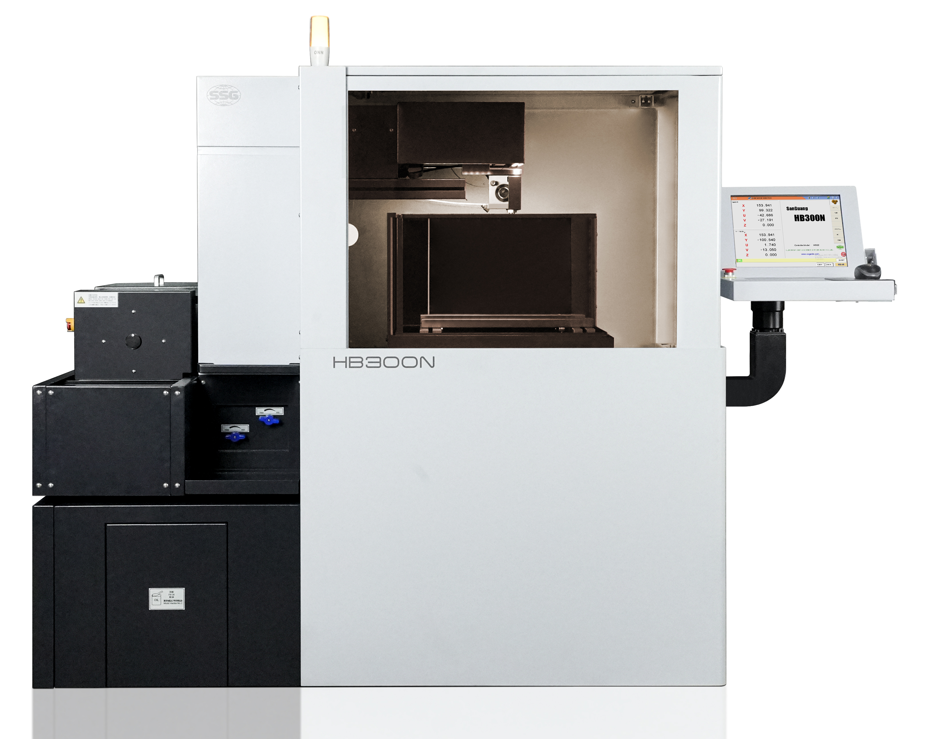
Understanding the primary tension management architectures available in the current market helps engineers select the right equipment for their specific tolerance requirements. The evolution of tension control separates entry-level machines from true precision instruments. You cannot expect aerospace-grade tolerances from a machine using a twenty-year-old tensioning design.
Traditional weight-based or spring-loaded friction-brake mechanical tensioners suffer from severe limitations. They are highly susceptible to physical wear, introduce mechanical lag, and completely lack real-time adjustment capabilities. A mechanical spring cannot react to a sudden thermal expansion event. As the friction pads wear down, the actual tension applied to the wire drifts away from the setpoint.
Modern closed-loop AC servo motor systems or electromagnetic hysteresis brakes actively monitor and adjust tension. These systems rely on continuous sensor feedback. If the tension drops by a fraction of a Newton, the electromagnetic brake instantly applies counter-force, keeping the wire perfectly taut regardless of external conditions. This active management is what allows modern machines to run unattended overnight without fear of wire breakage.
Advanced CNC controllers alter tension parameters dynamically based on the toolpath. When approaching sharp corners, transitioning through varying material thicknesses, or processing complex profiles, a static tension setting is inadequate. The machine must anticipate the physical load on the wire before the cut actually happens.
Programmable tension settings integrated into the machine's CAM software allow operators to match tension with specific cutting phases. A roughing pass requires different tension dynamics than a delicate skim pass. Dynamic control ensures the wire remains stable without snapping when cutting conditions change abruptly. For example, when the wire exits a solid block of steel and enters a pre-drilled cavity, the sudden drop in cutting resistance requires an immediate tension adjustment to prevent wire whip.
Reusable molybdenum wire gradually loses cross-sectional area due to continuous discharge-induced wear. As the wire becomes thinner, its maximum tensile strength decreases proportionally. A wire that starts at 0.18mm may wear down to 0.15mm after forty hours of cutting.
Advanced control systems calculate cumulative wire run-time and automatically scale down tension to match the reduced wire diameter. By actively lowering the pulling force as the wire degrades, these systems prevent premature breakage while maintaining enough tension to ensure accurate cutting. This feature alone can extend the usable life of a wire spool by 30%, directly reducing consumable costs.
Mapping specific tension behaviors to the physical geometry of the finished part reveals exactly why tension control matters. Every fluctuation in wire stability leaves a permanent physical signature on the machined component. When you inspect a failed part, the surface finish and dimensional errors tell a clear story about what the wire was doing during the cut.
During sharp directional changes, wire "drag" becomes a major issue. The center of the wire naturally lags behind the upper and lower guides as the machine axes pivot. If you are cutting a 90-degree internal corner, the guides reach the corner before the center of the wire does.
High, stable tension prevents corner washout, often referred to as radiusing. It forces the wire to track true to the guides, maintaining a strict, uniform kerf width throughout complex geometries. Without adequate tension, sharp internal corners become rounded, failing tight geometric dimensioning and tolerancing inspections. To combat this, operators use specific techniques:
Implement corner deceleration codes (G-code) to slow the feed rate as the wire approaches the pivot point.
Increase flushing pressure slightly to clear debris that might push the wire off course during the turn.
Ensure the tensioning system is calibrated to its maximum safe limit for the specific wire diameter being used.
Maintaining tension becomes exponentially more difficult when the upper and lower guides are offset along the U/V axes for taper cutting. The wire span increases, and the forces acting on the wire change direction. The wire is no longer pulling straight down; it is pulling at an angle against the guide wheels.
Uneven tension across this inclined wire span leads to geometric distortion during 4-axis cutting. Specialized hardware, such as tilting guides, is necessary to maintain Z-axis stability under high tension. If the guides cannot support the angled wire properly, the tension will fluctuate, destroying the accuracy of the taper. You will end up with a barrel-shaped taper instead of a straight conical cut.
Molybdenum wire boasts a high tensile strength, typically ranging from 1900 to 2300 N/mm². However, this strength is not infinite. You have to respect the physical limits of the material, especially when it is subjected to thousands of electrical discharges per second.
Localized spark erosion concentrates heat at specific points along the wire. The machine must balance maximum tension against the diminishing structural integrity of the wire. Pulling the wire too tight while it is weakened by localized heat guarantees a snap, halting production and requiring manual rethreading. We can map the relationship between wire diameter, wear, and safe tension limits.
Wire Condition | Diameter (mm) | Safe Operating Tension (Newtons) | Risk of Breakage at Max Load |
|---|---|---|---|
New Spool | 0.18 mm | 14 - 16 N | Very Low |
Moderate Wear (20 hrs) | 0.16 mm | 11 - 13 N | Low |
Heavy Wear (40 hrs) | 0.14 mm | 8 - 10 N | Moderate |
End of Life (50+ hrs) | < 0.13 mm | < 7 N | High |
Achieving maximum throughput requires balancing aggressive machining parameters with consumable longevity. Pushing a High Efficiency Wire EDM Machine to its limits exposes the conceptual trade-offs inherent in wire tensioning. You cannot maximize speed, accuracy, and wire life simultaneously; you have to choose which variable matters most for the specific job.
Higher cutting speeds demand higher flushing pressures to clear debris from the kerf rapidly. This increased fluid pressure pushes harder against the wire, necessitating higher wire tension to prevent deflection. If you turn up the discharge current to cut faster, you must turn up the tension to keep the wire straight.
Operators must evaluate the point of diminishing returns. Increased tension yields better accuracy up to a certain threshold. Beyond that point, the accuracy gains are negligible, but the risk of catastrophic wire failure increases drastically. A broken wire mid-cut on a weekend unattended run costs far more time than slowing the feed rate by 5%.
Running machines at maximum tension limits accelerates wear on critical machine components. The ruby or diamond guides, feed rollers, bearings, and conductive contact blocks all degrade faster under extreme mechanical loads. The wire acts like a microscopic saw blade, cutting into the guide wheels if the tension is too high.
This creates a hidden impact on operational margins. Frequent maintenance downtime and accelerated consumable replacement costs quickly negate the time saved by running at absolute maximum feed rates. Smart tension management preserves the machine hardware. You have to look at the maintenance log to see the real cost of running excessive tension.
Shop floor realities often complicate theoretical tension management. Operators face practical challenges that can undermine even the most advanced CNC systems if not properly addressed. A machine is only as accurate as its last calibration.
Relying on manual tension calibration, such as an operator's "feel" or rudimentary spring-scale checks, introduces massive variability. Human estimation cannot guarantee the exact Newton force required for precision work. One operator might set the tension at 10N, while another sets it at 15N for the exact same job.
Implementing standardized tension-check protocols using digital tensiometers eliminates this guesswork. Investing in machines equipped with automated self-calibration routines ensures the baseline tension is accurate before the first spark is ever generated. We recommend the following calibration routine:
Clean all guide wheels and conductive blocks with a specialized solvent to remove carbon buildup.
Thread a fresh section of molybdenum wire through the transport system.
Engage the tensioning system to the standard roughing setpoint.
Apply a digital tensiometer to the center of the wire span and verify the reading matches the controller output.
Adjust the mechanical baseline or software offset if the reading deviates by more than 0.5 Newtons.
Groove wear on tension rollers and slip on the wire drum lead to false tension readings and micro-slippage. If the wire slips over a worn roller, the closed-loop system receives inaccurate feedback. The controller thinks it is pulling at 12N, but the wire in the cutting zone is only experiencing 8N.
Strict preventive maintenance schedules are mandatory. Regularly inspecting and replacing guide wheels, tension pulleys, and wire collection components ensures the mechanical transport system accurately reflects the tension commanded by the CNC controller. You should visually inspect the V-grooves on the guide wheels every 100 hours of operation.
Temperature fluctuations in the shop environment cause thermal expansion or contraction of the machine casting itself. This subtly alters the distance between the upper and lower guides, affecting baseline tension. A machine calibrated at 65 degrees Fahrenheit will behave differently when the shop heats up to 85 degrees in the afternoon.
Furthermore, changes in dielectric fluid viscosity, often due to temperature shifts or debris contamination, alter the drag force exerted on the wire. The tension system must compensate for these environmental variables to maintain consistent cutting conditions throughout long production runs. Maintaining a climate-controlled environment and utilizing a high-quality dielectric chiller unit are standard practices for precision EDM work.
Request a test cut from the manufacturer utilizing a stepped-thickness part with sharp internal radii to empirically verify the machine's dynamic tension control capabilities.
Consult with an applications engineer to review the specific tension parameters required for your most common materials, such as tool steel or tungsten carbide.
Implement a strict maintenance schedule for all wire transport components to prevent mechanical wear from degrading tension accuracy.
Equip your operators with digital tensiometers to verify baseline tension settings independently of the machine's internal sensors.
A: Modern closed-loop machines utilize inline load cells and tension sensors to continuously monitor force in real-time. For manual verification, operators use handheld digital tensiometers pressed against the wire span to measure the exact tension, typically displayed in grams or Newtons.
A: Optimal tension depends on wire diameter, material thickness, and flushing pressure. Generally, it ranges from 12% to 20% of the wire's ultimate tensile strength. For a standard 0.18mm molybdenum wire, this typically equates to a running tension of 10 to 15 Newtons.
A: Wire breakage at corners is usually caused by a combination of high tension, wire lag, and concentrated spark erosion at the pivot point. To fix this, lower the tension slightly or utilize the CNC controller's automatic feed-rate reduction (corner deceleration) feature during directional changes.
A: Drum reversal causes a momentary pause and a sudden tension drop, leaving a visible "reversal stripe" on the workpiece. Modern machines solve this using fast-acting electromagnetic brakes or dual-tensioning units that instantly pre-tension the wire before the drum resumes travel.
A: No. Increasing tension cannot fix positional inaccuracy caused by worn, grooved guides. Attempting to do so will only accelerate guide wear, damage the wire surface, and drastically increase the likelihood of wire breakage.
A: Molybdenum has a significantly higher tensile strength than brass and runs in a reusable, bidirectional loop. Consequently, molybdenum systems must manage dynamic tension drops during drum reversals and gradually reduce tension as the reusable wire wears down over time.
 HB400
HB400  HB600
HB600  HB800
HB800  LA350A
  LA500A
  LA800
LA800  EB450
EB450  EA500A
  EB650N
  DS703C
  SK450
SK450 


